Fuzzy Fruit Picker (aka Crabby)
Mattie Lee (mll264), Eshita Sangani (ens57), Janeth Manyalla (jim59)
Demonstration Video
Objective
Create a robotic arm to identify different colored "fruits" (colored puff balls) and sort them into bins.
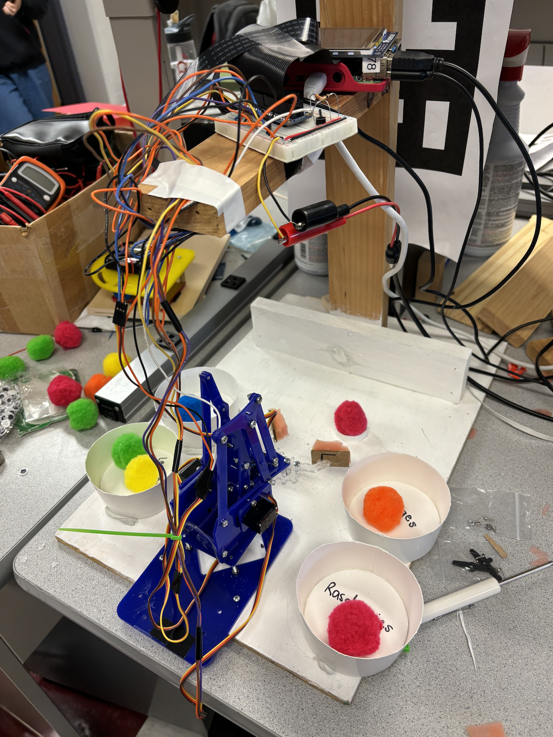
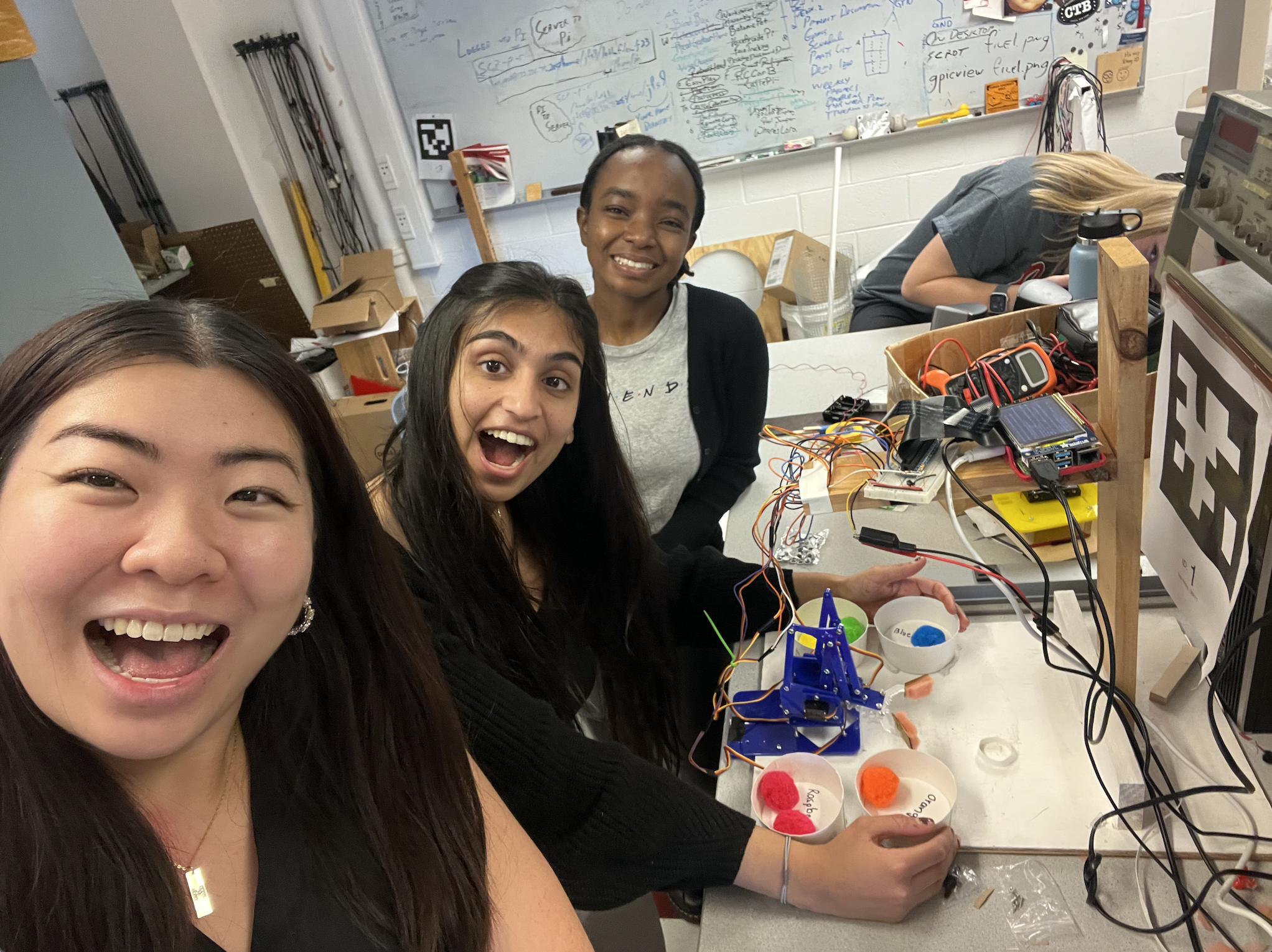
Final System Setup
Introduction
Using a Raspberry Pi, this project utilizes the PiCamera for color detection of various fruits (as puff balls) using OpenCV. Once the fruit is identified, the meArm robotic arm uses inverse kinematics to sort them into different bins, by enabling precise control of its servo motors. The code also incorporates GPIO event handling, allowing the user to exit the program or shut down the Raspberry Pi using external buttons.
Design and Testing
After having a rough idea and sketch of what we were going to build, our project went through different stages of design and testing that are outlined in the phases below.
Phase I: MeArm Robot Assembly & Servo Testing
To enable our picking mechanism, we decided to use the MeArm Robot v1.0 kit. We chose the MeArm robot design because it is a simple and sturdy enough structure for the purpose of our project, which used colored small, fluffy, light-weight pom poms to represent different types of fruits. The arm is designed with three Degrees of Freedom (3DOF), a square-like base with a pivot center to rotate the arm from left to right accordingly and elbow and shoulder pivots to elongate or shorten the gripper’s reach around a three-dimensional coordinate space. We used four standard servo motors with an angle range from (-π, π) radians for the three pivots and the gripper.
After consultation with Prof. Skovira, we were able to acquire the MeArm robot kit from a previous project that used a similar design but was missing a gripper, which we were then able to obtain through laser-cutting a plastic sheet using available open-source CAD design for the v1.0 kit. Since most of the arm was already pre-assembled, we disassembled parts of the arm to test the servo motors and also assembled part of the gripper and tested its functionality. After testing the servos, we assembled the full robot arm and configured the servo positions to particular angle degrees to ensure that the arm does not stretch and withdraw that it collides with its base or other areas beyond its reach.
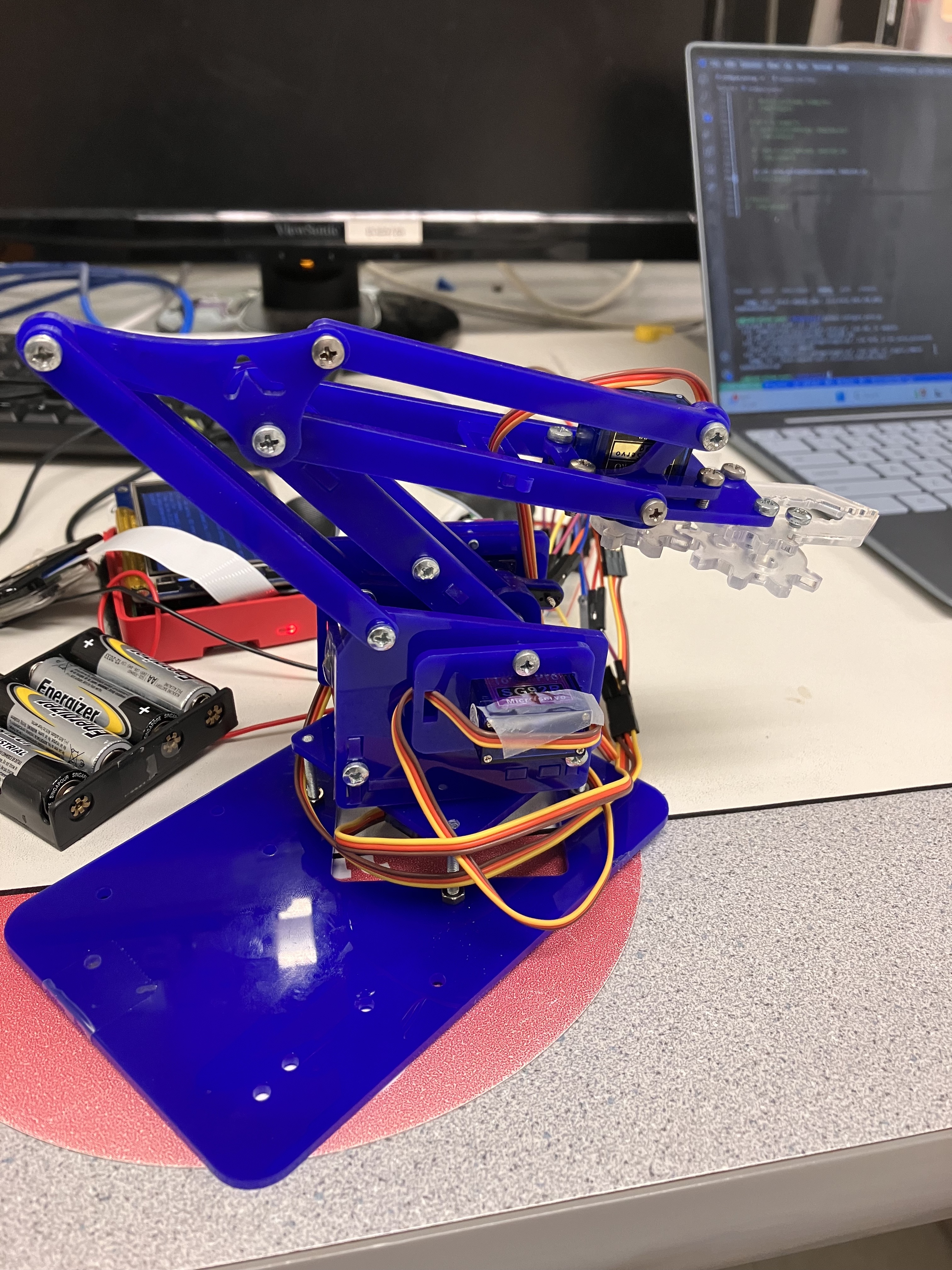
MeArm Robot After Assembly
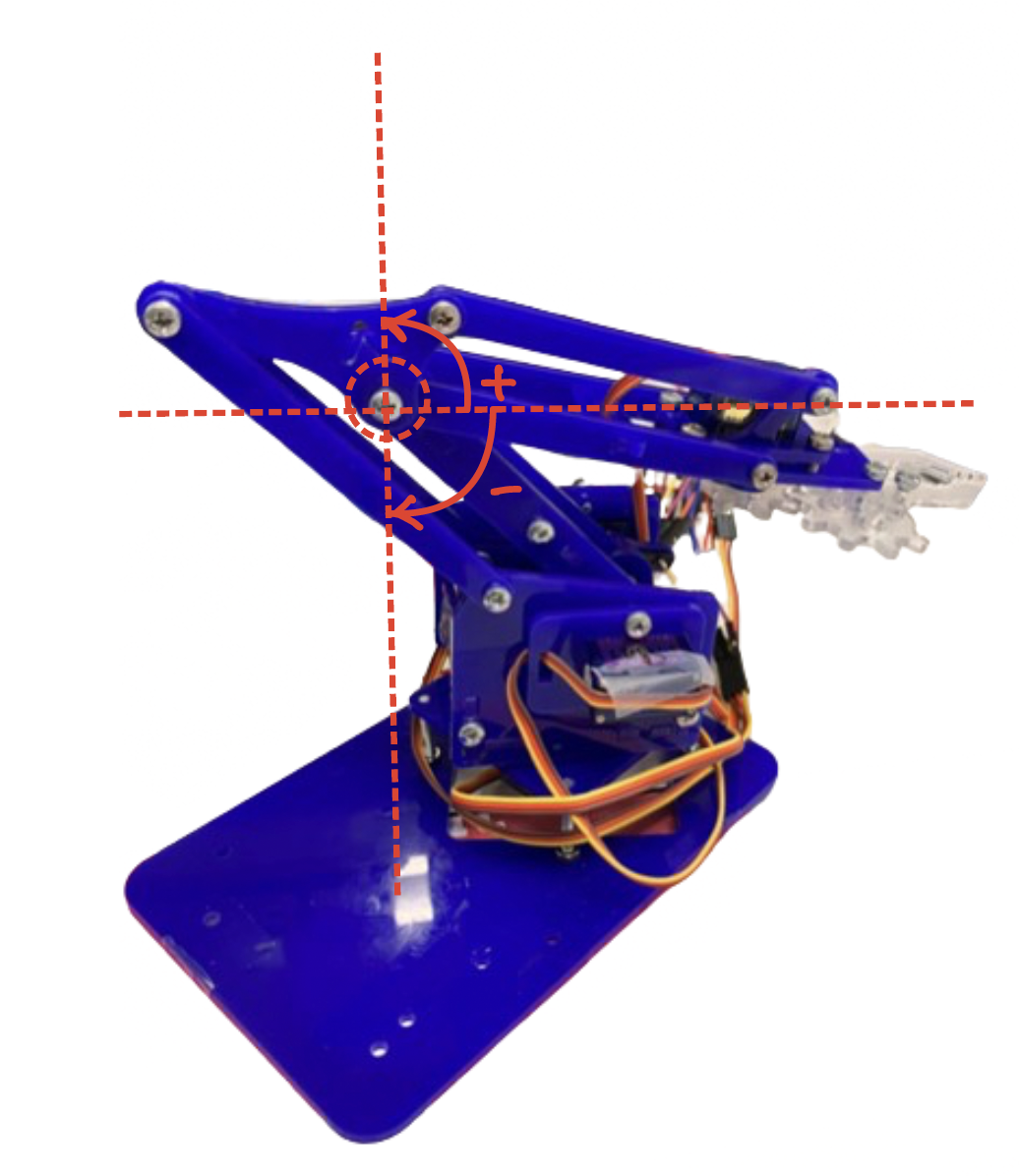
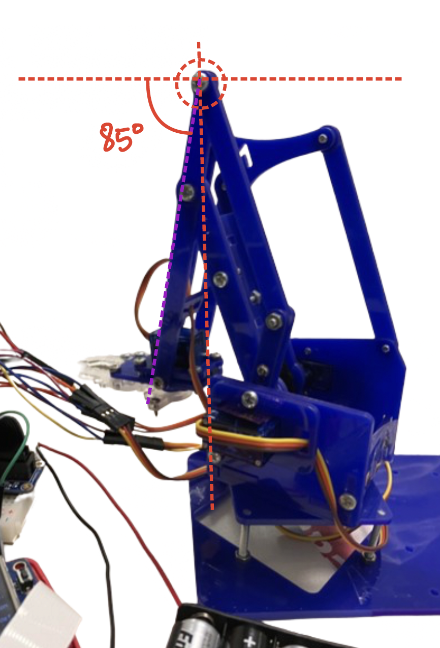
Figure 2: Configuring the elbow (left) and shoulder (right) servo motors
Phase II: Designing & constructing the testing environment
Since our project required the arm to move around, we needed to attach the robot base to a heavier base to keep it stable during implementation; therefore, we screwed the base to the edge of a rectangular piece of wood, which also provided an arena where we could place the fruits and buckets that the fruits will go into when sorted. For fruit detection, we used a Raspberry Pi Camera module that needed to be placed at an overhead position to capture the color and position of the fruits in the testing space. For that, we used a vertical wooden structure that was placed some distance in front of the arm position and attached a horizontal overhang that we used to hold the camera below and the Raspberry Pi, battery pack (when needed), and breadboard with circuit connections on top.
Since the OpenCV color HSV masks we created for the fruit colors were tested on a white background, we painted the testing ground white to enable accurate color detection. We then tested the color_detection.py code to ensure it worked as expected and adjusted accordingly for accurate results.
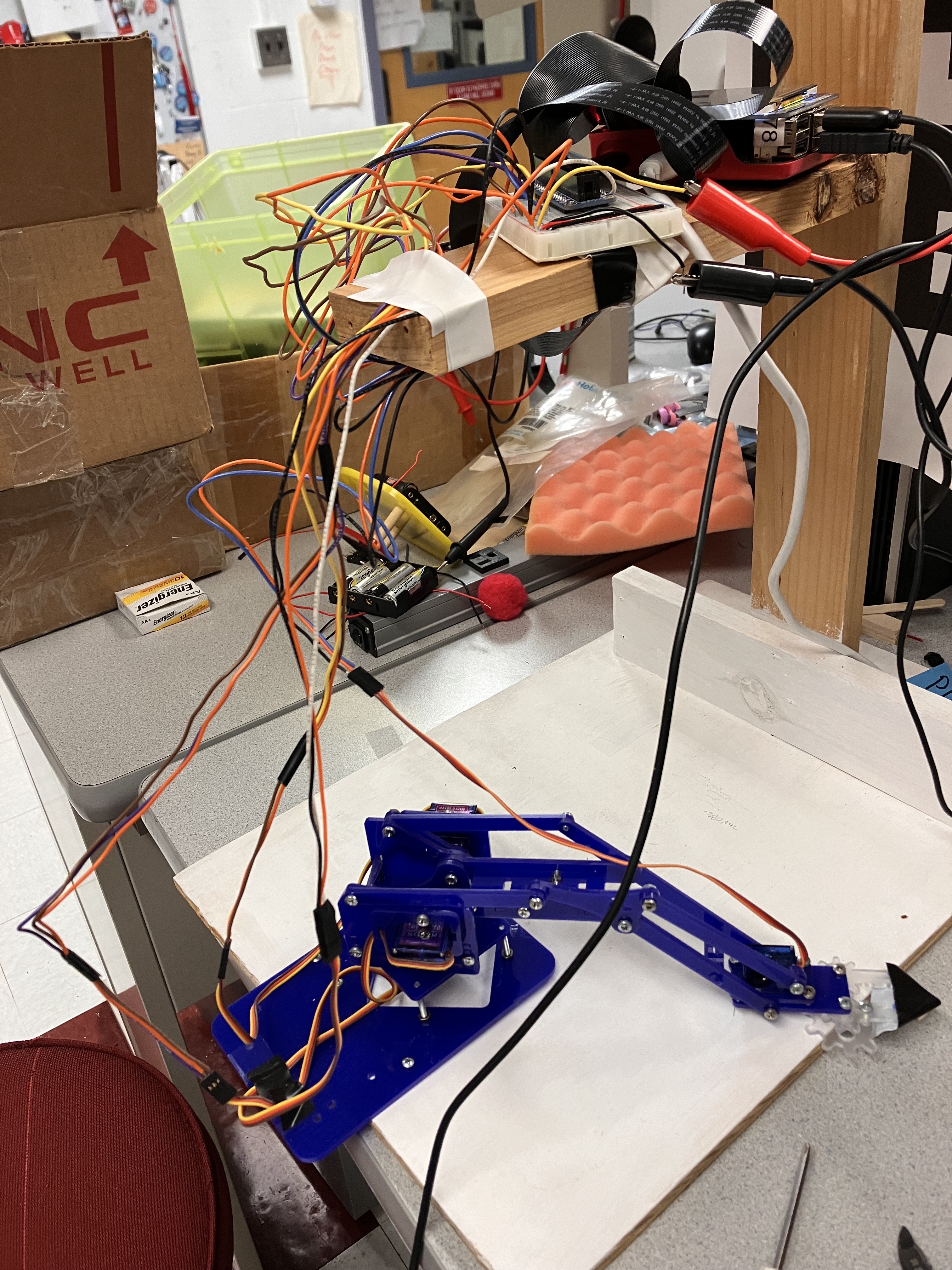
Figure 3: Testing environment
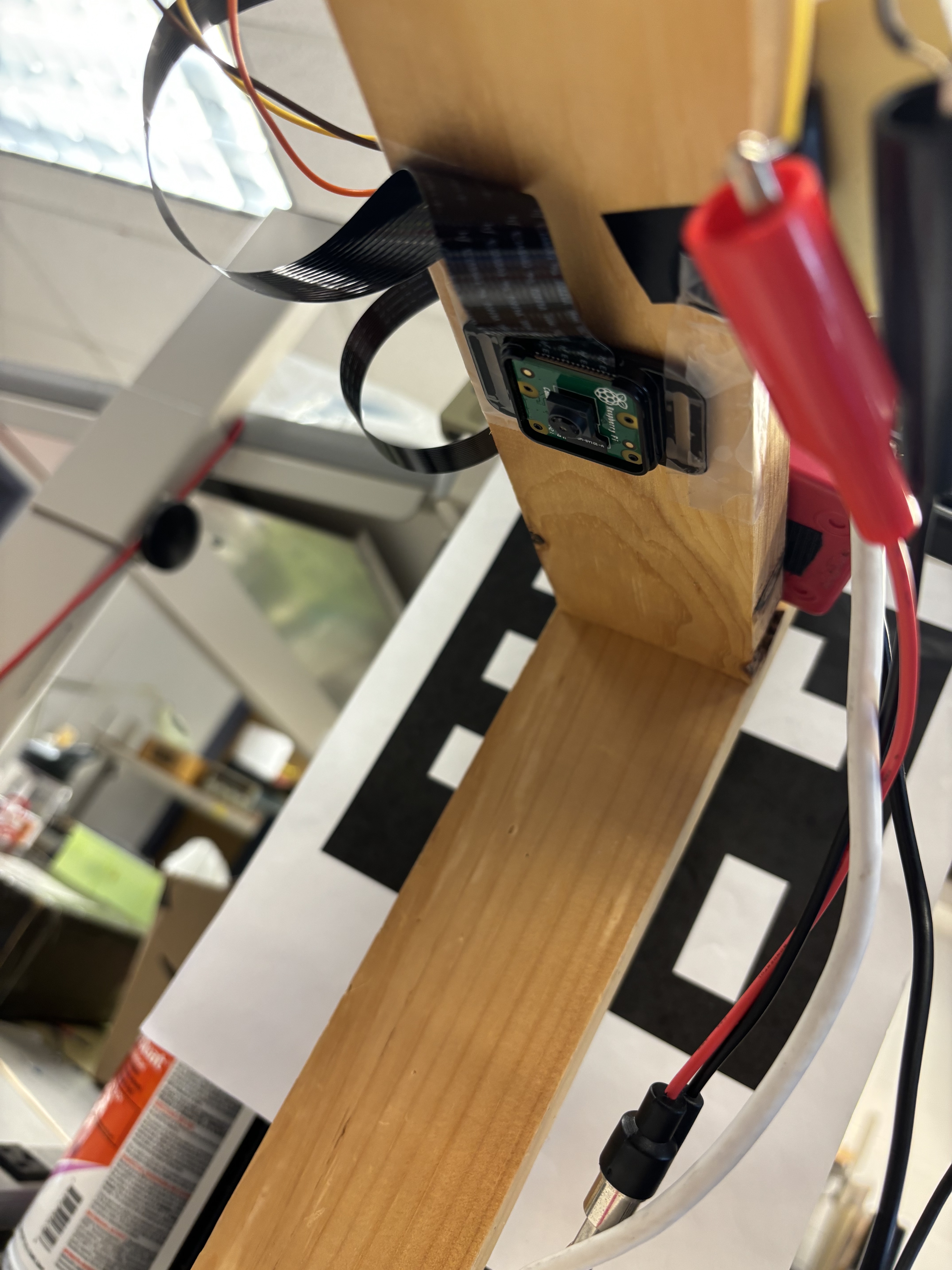
Figure 4: Camera attached below horizontal overhang
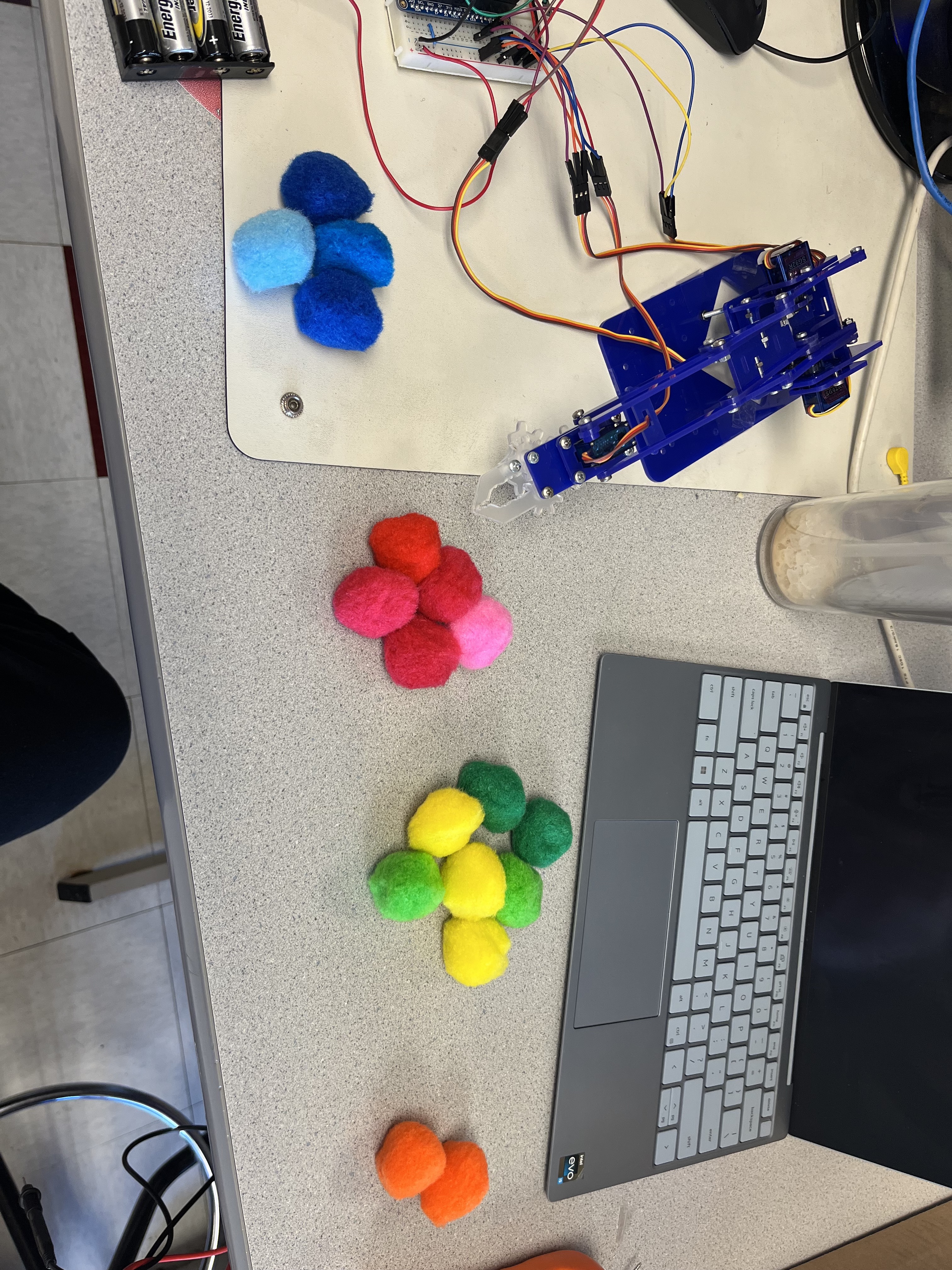
Figure 5: Test fruit groups, left to right: Blueberries, Raspberries, Lemons/Limes, Oranges
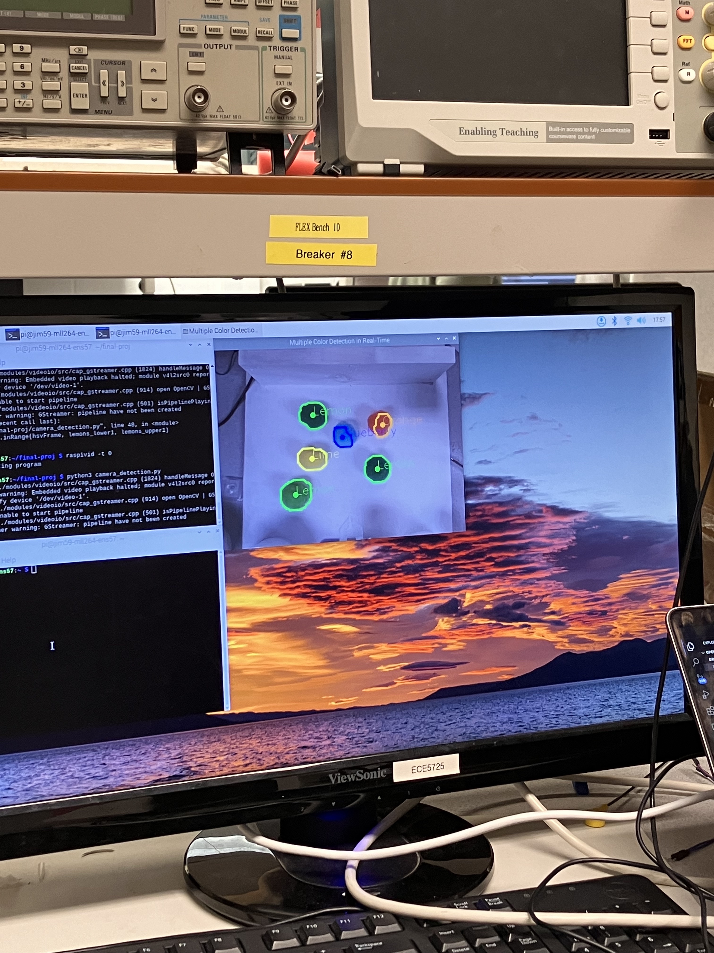
Figure 6: Testing color detection in environment
Phase III: Integration & Project Evolution
After creating the environment, we then integrated the whole project to test the functionality of the camera using OpenCV and robot arm motion using inverse kinematics whose code contents are described in depth in the Software Design section. During testing, we had four paper cups for buckets for the four test fruit groups where the arm would drop the contents during sorting.
After the camera detects a particular fruit, it assigns x and y coordinate positions of the fruit in camera reference. Since the robot arm operated in its own coordinate system, the camera pixel coordinates needed to be translated into robot coordinates for the arm to move to the exact position of the fruit. In robotics, the process of mapping the camera pixel coordinates into robot base coordinates involves the calculation of a homogeneous transformation matrix, ensuring the camera is parallel to the testing surface, and adjusting the camera image distortion as needed. However, embarking on such an adventure would have required a good amount of time that was not on our side at this stage of the project. Instead, we opted for a test-and-trial method where we tested the scaling of the camera coordinates using constant variable values to get the x and y coordinates from the robot base, which we chose to be the base servo pivot.
Following coordinate scaling, we incorporated the inverse kinematics with the camera detection code and tested the robot arm motion after color and object detection. After several testing iterations, the main problem we faced was inaccurate adjustments of the servo motors when mapped to the same positions, which caused the robot to accumulate an error and be slightly off. It is possible that the accumulated error was caused by our use of open-loop inverse kinematics instead of closed-loop, which meant the robot did not know its position after movement and therefore did not adjust its final position which got worse with each iteration. We reduced the inaccuracy in our code by adding an error value to accommodate the position shift.
In reference to our project proposal, the initial idea was to set the fruits in a row or at random locations on the test table where they would be picked by the robot arm into sorting bins. However, since we were facing slight troubles to ensure accurate arm position, we decided to adjust the initial idea by instead designing a simpler working model, which we could build on during later stages. We therefore decided to map the robot to a single coordinate position where it could pick up a single fruit and drop it into its corresponding bin location. For a completely autonomous system, we thought of having a fruit dispenser that would drop another fruit after the arm had picked it up, however, we soon realized that it was likely that the fruit would be dropped or displaced to a different location as the arm moved to and from the fruit position. Hence, we opted for a semi-autonomous operation where we placed the fruit in the position to be detected by the camera, then picked by the robot arm and sorted to its particular bin/bucket. We also placed a hollow, circular paper structure on the picking position to keep the fruit stable during picking and remodeled the gripper with small rectangular flaps using box and sponge material for a tighter and non-slippery grip of the fruit during arm motion. We then tested moving the robot arm to the position several times, opening and closing the gripper before or after reaching the location, fruit detection, and its type if available, and picking up and dropping the fruit to its particular bin that worked successfully after several iterations.
Figure 7: Final Project Design
Final Design Overview
Software Design
Our final software design consisted of two main files: ik.py, which implemented our inverse kinematics algorithm, and full_demo.py which integrated the color detection algorithm with ik.py. We separated the inverse kinematics into its own module to compartmentalize the movement functions.
ik.py
Diving into the ik module, it first initializes servo configurations using the Pigpio library, assigning GPIO pins to control the gripper, shoulder, elbow, and rotation servos. Servo-specific variables such as open/close pulse widths, ranges, and midpoints are defined to calibrate their movement. The MeArm operates in a Cartesian coordinate system, with the origin set above the base ROTATE servo. The x-axis extends to the right, the y-axis points forward, and the z-axis represents an upward direction. For the kinematics calculations, we found inverse kinematics equations for the MeArm in the open-source repository me-arm-ik. We converted these calculations into Python functions that were then integrated into a larger function (solve()) that took Cartesian coordinates as inputs and outputted the three joint angles for the MeArm. However, we then had to create a separate function (ang2pulse()) that transformed these joint angles into the servo pulse widths that we could send to the servos.
full_demo.py
This is the script that is executed that combines the camera detection with the inverse kinematics that was discussed above. The script initializes the webcam using OpenCV's VideoCapture and sets a conversion factor MM_TO_PIXEL for converting millimeters to pixels in the image which is the mapping of the camera coordinates to those of the robotic arm coordinate system (the main integration). The main operation of the script is within the main while loop which operates continuously as long as the code_run variable remains true, and it is only set to false if the quit or shutdown buttons are pressed. Within each iteration, it reads frames from the webcam, sets a static position, and calls the detect_fruit function to update global flags based on detected fruits. Conditional statements then determine which fruit is detected and trigger corresponding actions using inverse kinematics functions. After performing the inverse kinematics actions, the script reads a few more frames from the webcam (for i in range(5):) with a delay of 1 second (time.sleep(1)) to allow the robotic arm to complete its movement. This is a simple way to update the webcam feed and show the arm's motion over time. The flags (rasp_flag, blue_flag, etc.) are reset to False after performing the corresponding actions. This prevents repetitive execution of the same action until a new fruit is detected. The loop continues until an external event alters the code_run variable, prompting cleanup procedures for OpenCV windows and GPIO resources.
The detect_fruit function is the implementation of the camera module. For the camera module, we first needed to implement color detection using OpenCV. This was done by creating color masks to isolate regions in the webcam feed that match the color characteristics of raspberries, blueberries, lemons/limes, and oranges. For each type of fruit (raspberries, blueberries, lemons/limes, oranges), we defined specific upper and lower bounds in the HSV (Hue, Saturation, Value) color space. Then we used morphological operations to process the images by removing extra noise and simply making the detected areas more prominent, to increase the likelihood of identification. The last processing step was to use bitwise AND to isolate regions in the image that match the color characteristics of the predefined masks, ensuring that we get the correct colors. This color detection chunk of code needs to be inside the while loop so that it is constantly being executed and can quickly and accurately detect the colors.
Hardware Design
The two main components of our design are the mechanical arm, the breadboard and Raspberry Pi along with its wiring, and the camera. The mechanical design was explained in the earlier section and the only changes made were replacing the regular servos with high torque servos, allowing for more precise control. Each servo was controlled with a specific GPIO pin - the Gripper was 26, the Shoulder was 5, Rotate was 16, and the Elbow was 13. These were chosen so that they do not interfere with the functionality of the pi and its tft screen as well. In addition, we used button 17 from the piTFT screen as the shutdown button and an external pull down button using 1kΩ and 10kΩ resistor connected to GPIO 21 as the quit button to cleanly exit out of our program to the console.
As seen in Figure 7, the wires needed to be extra long so that the pi could sit on top of the wooden structure and not interfere with the movement of the arm. All the wiring for the servos, other than that of the Gripper, were zip tied and taped to lessen the possibility of them being disconnected.
Results
Since the final demonstration of the project varied from the initial proposed idea, it is safe to say that there are some things that changed along our project implementation. The goals outlined in our project proposal included creating a Linux-based autonomous robotic arm that sorted ripe/unripe fruits into buckets. By the end of our project, we have been able to design and build a semi-autonomous Linux-based robotic arm that accomplished the goal we had set, to sort fruits into buckets/bins. One of the things that changed was implementing a semi-autonomous embedded system instead of a fully-autonomous system, which means we sorted our fruits from a particular position where we manually placed them. From the beginning, we planned to use inverse kinematics for robot arm motion and OpenCV for color detection and object tracking which we have been able to achieve.
Conclusion
Overall, our project was a success. Despite the simplifications that we made, this project taught us a lot about various topics within robotics as well as Embedded OS systems. We gained more experience with using OpenCV, worked extensively with servos, became familiar with the pigpio library, and learned about inverse kinematics. Although this project was challenging, it was the perfect capstone to our experience in this course.
Future Work
If we had more time on the project, we would have integrated the camera with the arm completely so that it would be able to sort the balls from any position within the visible range of the camera. The other challenge that we faced was smoothening the moment of the arm and the next steps for that would be to implement PID control.
Bill of Materials
Raspberry Pi 4
Adafruit PiTFT
MeArm Robot Arm
Raspberry Pi Camera Module
Raspberry PI B+ GPIO Adapter Plate 40-Pin for Breadboard Expansion Board
GPIO Ribbon Cable
4 standard servos
2 Breadboards
Bag of Fuzzy Balls ($10)
Resistors (10kΩ + 1kΩ)
Wires
Wooden structure
Github Repository!
Group Members
Mattie Lee

Eshita Sangani

Janeth Manyalla